Robotic Vision
Computer Vision for Hobby robots
Basic CV based line following The Open Source Image processing library – OpenCV was used to build a RaspberryPi Based Line Follower Bot. This Bot was controlled by Raspberry Pi. The various algorithms for line following were tested out. All of them processes only the required part of the image and thresholded that part as the first step. But rest of the steps had few variations Centre of gravity (CG) of the line used to calculate the angle of deviation of the bot. CvCanny was used and CG of Edges was used to obtain the angle of deviation CvContours was used to find out the CG of the contour
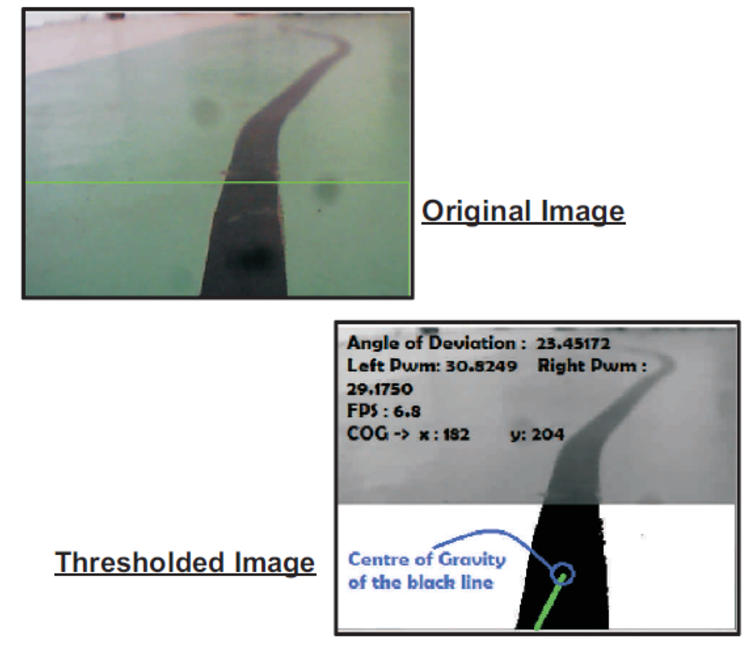
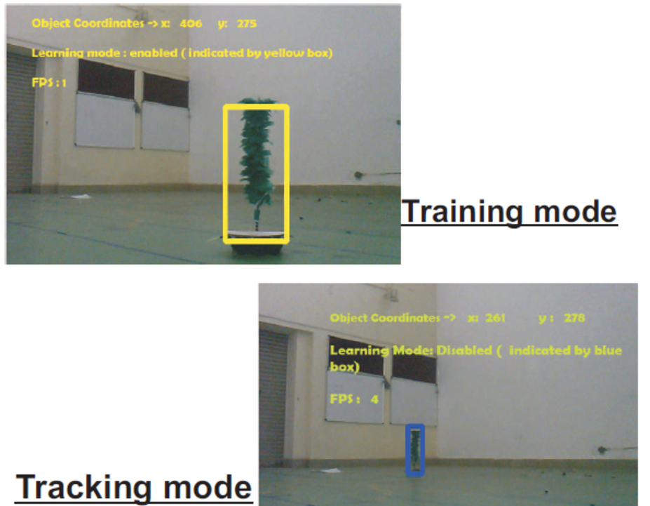
Camera video is first converted as different frames of colour pictures. These pictures are converted to an 8-bit grayscale image. Then it is converted to a binary image ( Black and white) by the following procedure -> If a pixel value is above a threshold value, the pixel is set as white, else it is set as white. This threshold value is given by the user in command line arguments. This was used only for testing purpose. In the real-time application, intelligent autonomous calibration of threshold value was used. The bot was tested for different lighting conditions and adaptive threshold values for the image was implemented. The information about the lighting conditions was obtained using a 'Light Dependent Resistor' (LDR). Thus, the real-time and adaptive threshold value can be automatically calculated by the program. Thus after these operations, we get a noiseless binary image. In this image, Centre of Gravity (CG) of black pixels up to a certain height of the image ( due to the fact the only those parts of the line which are close to the bot must affect its motion) is calculated. This height is passed as a value to a function in the program. The Bottom left and top right coordinates of the canonical rectangle of the region in which the line is also passed as a parameter to the function. The deviation of the centre of gravity of black pixels is then calculated. The deviation is nothing but the difference between the centre of gravity of black pixels can centre point of the frame. This gives the deviation from the centre. During mounting, the centre of the camera is to be aligned with the centre of the bot. We can not exactly set that, only if CG of black pixels and Centre of the frame are same, the bot must go straight. This is practically not feasible because of two reasons 1.) We are dealing with floating point variables. This can have floating point errors 2.) Exact centre may be very difficult to achieve So, a different variable called ERROR to set how much a bot can deviate. This also depends on the width of the line to be followed. The deviation and direction of deviation are then sent to the Arduino. This data is used to allow a Pulse Width Modulated (PWM) power signal to motors. The camera is mounted such that the lens is parallel to the ground and the bottom-most part of the image is almost in line with the tip of the bot chassis. This ensures that when the bot is totally aligned with the line i.e zero position, the deviation and the angle obtained from the image should both be zero. The results obtained are depicted in the image below. It works on a max PWM of 12% duty cycle on mechtex motors. Above which the capture from the camera is not fast enough. Using Pi cam definitely improves the max PWM and the runtime of the code. It was also realised that there is a quadratic relationship between pwm of motors and angle of deviation. i.e PWM of motor 1 = Normal Pwm - (k * angle^2) and PWM of motor 2 = Normal Pwm + (k * angle^2) Next step is cvCanny and Hough Transform was used. These helped to reduce the unwanted noises in the image. The bot was able to follow smooth lines at the max pwm of 12%. Lessons learned Some of the other experiences gained from this task were:- Never Run any code from SD card of pi. always run codes from pen drive. Attach a pen drive to USB slot of Pi, mount it and run codes from it. If codes are run from SD card, ( wiring pi requires SuperUser rights to run ) these may damage boot files of Pi in SD card, thus corrupting it. Code must be run by the RPi without tranmitting any feed through ssh. Transmitting feed through ssh consumes 50% of the processing power of Pi. Powering Pi must be free of any loose connections. As any drop in voltage below 4.2V would KILL any process running in it. It would be troublesome to start the pi again. And moreover, it may corrupt the SD card. Camera Mount must be very rigid Sufficient lighting must be provided for the image.We achieved it using LED strips. Pattern tracking OpenTLD algorithm used to detect and track various objects. Initially, the object of Interested is manually detected and used to train the algorithm. Once, it is able to detect the object of interest in a wide set of backgrounds, it is then used to track the object real-time.The algorithm is used to get coordinates of pattern and move bot towards the target.The pattern detection-cum-tracking library OpenTLD which was tested in raspberry pi turned out to be relatively slow. ( 3-4 fps in tracking mode and 1-2 fps in learning mode) but nevertheless yielded accurate results.
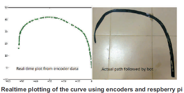
Machine Learning Simple ML algorithms (from the PyML library) were used to replace curve tracing using sensor by machine learning algorithms. In this, first, the bot was made to move on the curve using any method and note the encoder vs. velocity readings for learning of a machine. The bot then learnt from a large number of trials and was able to trace the curve with given encoder values. This method also proved to be useful in Auto-Tuning PID.